Troubleshooting
DANGER
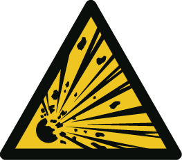
Risk of explosion
In explosive atmospheres, human error can result in an explosion.
- Make sure the type of actuator used meets your requirements for the explosion-protected area. You can find this information on the actuator label.
Ex…: ATEX Zone 1, 2, 21, 22;
Red…: ATEX Zone 2, 22;
In…: not suitable for the explosion-protected area! - As far as possible, avoid working in an explosive atmosphere.
- Disconnect the actuator from the power supply before carrying out any work on it in an explosive atmosphere.
- Make sure that installation and connection work is only carried out by appropriately trained skilled personnel.
- Always work adapted to the ambient conditions.
- Work in active potentially explosive atmospheres must be approved by the operating company.
DANGER
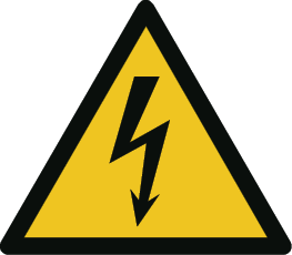
Risk of death due to electric shock and short circuit
Damage to the cabling or incorrect installation can result in an electric shock or short circuit and fire/explosion.
- Make sure the electrical connection and integration of the control unit are only carried out by appropriately trained specialist personnel.
- Please ensure the cables are laid without being damaged. Bear in mind external influences on the cables and use appropriate cable ducts or cable trays.
- Make sure the wiring is done correctly (see circuit diagrams).
- Before commissioning/starting up, make sure all cables and the drive are undamaged.
- Remember the five electrical safety rules:
Unlock
Prevent it being switched back on
Ensure no voltage at all
Earth and short-circuit
Cover or block off adjacent parts that are still live.
WARNING
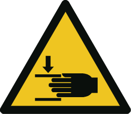
Risk of crushing and impact
In the event of a power outage, the rotary drives with spring-return mechanism will return suddenly to their initial position. This can result in crushing or impact injuries if work is being carried out on the rotary drive and its connected assemblies at this time.
- Disconnect the power to the rotary drive before starting work. Make sure that nobody is working on the rotary drive or the connected assemblies (e.g. ventilation flaps) at this time.
- Only carry out work when the rotary drive spring is not under tension and is in its initial position.
WARNING

Risk of crushing and impact
If the Allen key is inserted, this can result in crushing and impact injuries in the event of unexpected start-up of the drive.
- Before starting work, disconnect the drive from the power supply to prevent an unexpected start-up.
- Remove the Allen key immediately after use.
WARNING

Risk of crushing and impact
If the actuator starts up unexpectedly, crushing injuries can occur at the connected assemblies.
- Potential crushing points should be considered in the integrator’s risk assessment.
- Check whether additional protective measures are necessary.
- Before beginning work on the actuator, make sure it is completely disconnected from the power supply to prevent an unexpected start-up.
- Make sure the actuator is assembled correctly.
- Check that the actuator fits on the fitting.
WARNING

Risk of impact
If the drive falls wile work is being carried out, it can hit and injure someone.
- During installation and when dismantling, make sure nobody is located below you.
- During the installation, make sure that the drive cannot loosen or detach itself. The same applies over longer periods, taking into account external influences such as vibration, corrosion etc.
WARNING
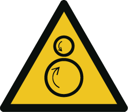
Finger twisting
At the open end of the shaft, there can be unexpected rotational movements, e.g. if the rotary drive is accidentally switched on or if the return spring is triggered by a power outage.
- Never stick your fingers into the open end of the shaft.
- Only operate the rotary drive once it is installed.
- Turn off the power to the rotary drive before starting work to avoid it being started unexpectedly.
CAUTION

Possible damage to musculoskeletal system
Working in positions with an adverse body posture can result in orthopaedic injuries.
- Make sure you are working as ergonomically as possible.
- Use appropriate tools, e.g. steps for easy access.
- Wear personal protective equipment: headgear and gloves.
CAUTION

Impact and tripping hazard
If the drive is not positioned carefully, it can pose an impact and tripping hazard.
- As far as possible, avoid installing the drive in the area of footpaths or work areas.
- Position the drive so that it does not cause any risk of tripping or head impact.
- If necessary, provide warning indicators or padding around any potential impact points.
Problem | Possible causes | Resolution strategy |
|---|---|---|
Drive does not work, LED not lit up | There is no power supply | Connect the power supply and switch it on |
The actuator is operated at an ambient temperature outside the specifications and the internal thermal cutoff has been irreversibly triggered | Impermissible operation has resulted in the actuator being put into an irreversible state for safety reasons, and the actuator must be replaced. For the new installation, the ambient temperature must be reduced at the same time | |
Drive does not work, LED is red | The actuator is operated at an ambient temperature that is too high, resulting in the internal temperature sensor being triggered | Switch off the actuator and allow it to cool down, take appropriate steps to lower the ambient temperature, e.g. by ventilation or a different mounting position |
To function, ...-BF drives need a temperature trigger of type ...Pro-TT or FireSafe | Connect the trigger, LED turns green, drive is ready for operation | |
Drive does not work, LED is green | 3-point control signal connected to both inputs | Correct the circuit |
The required torque is greater than the torque supplied by the drive | Configure a higher torque on the drive, if this is available, or replace the drive with a type offering a higher torque | |
Control signals do not fit or are on the wrong wire | Check the control and actuator signals and connect as per circuit diagram | |
The actuator has been installed incorrectly and is blocked by an external stop | Uninstall the drive, check that it works without any load, then install it in such a way that power can be transmitted from the drive to the fitting/valve that needs to be moved without any external impediment or torsion | |
Power supply connected to the wrong poles | Cables reversed: 1 must be connected to (−, N) and 2 to (+, L) | |
Actuator is not running, LED is flashing red | The actuator was installed at temperatures < -20 °C and has not yet reached its operating temperature of at least -20 °C | Ensure there is a constant power supply to wire 1–2 |
Wait until the necessary operating temperature has been reached by the actuator’s internal heating. The actuator then starts to work independently | ||
Y-drive cannot start intermediate positions in 3-point mode | The switch from continuous mode to 3-point mode has not been made | Set the drive parameters in accordance with the installation instructions |
Drive is in a skewed position on the square damper shaft | The drives have an angle of rotation of 95° incl. 5° pre-tensioning. The pre-tensioning was not taken into account during installation | Remove the drive from the damper shaft, use the Allen key to manually raise it by approx. 5° before placing it on the damper shaft for attachment. Follow the installation instructions! |
A Y-continuous drive which works with a restricted angle of rotation reaches its end positions already at > 0 V / 4 mA or < 10 V/20 mA | No adjustment of the angle of rotation was made during commissioning | Adjust the angle of rotation in accordance with the installation instructions |
LED flashes irregularly, actuator is not running | Actuator is not receiving sufficient supply voltage | Increase the wire cross-section or the voltage at the transformer/power supply output |
Wiring too long, excessive drop in voltage in the supply cable | Increase the wire cross-section or the voltage | |
Only for size S: | ||
Spring-return function is 10 s/ 90°, but should be 3 s/ 90° | Bridge 2–5 missing | Bridge wire 2 for the constant voltage supply with wire 5 |
Spring-return function is 3 s/ 90°, but should be 10 s/ 90° | Bridge 2–5 installed | Remove bridge |
Drive will not start up after more than 2 brief sequential setting functions in 3-s mode | The maximum permissible duty cycle of 1 minute break after 3 sec. motor runtime was not adhered to, the drive is in safety shutdown mode | Wait roughly 1 minute for the internal electronics to cool down to operating temperature again |
Drive has been installed with clamping device KB-S so it is friction-locked on the damper shaft and is only partly functioning or not at all | Assuming the aforementioned basic electrical conditions have been met, it is possible the rotation lock has been installed such that the drive is tensioned and impeding itself due to the non-central axle connection | Loosen the rotation lock and install it so that the drive can execute a slight oscillation around its angle of rotation |
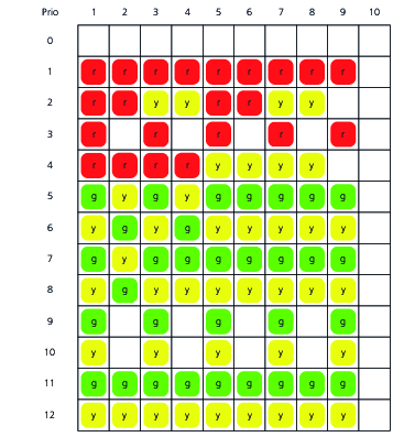
The following figure shows the possible flashing sequences of the multi-coloured LEDs, the table shows the meaning of the sequences. In the figure, each square is equal to an interval of 100 ms.
0 | Drive is idle |
1 | Internal error – notify service. |
2 | Internal error – notify service. |
3 | Internal error – notify service. |
4 | Fire protection is active, contact BF is open |
5 | Blockage at top |
6 | 3-point execution with Y feedback: Blockage at top |
7 | Blockage at bottom |
8 | 3-point execution with Y feedback: Blockage at bottom |
9 | Adjustment run |
10 | 3-point execution with Y feedback: Adjustment run |
11 | OK |
12 | 3-point execution with Y-feedback: OK |